Shore Power Ground Fault Monitoring | Bender
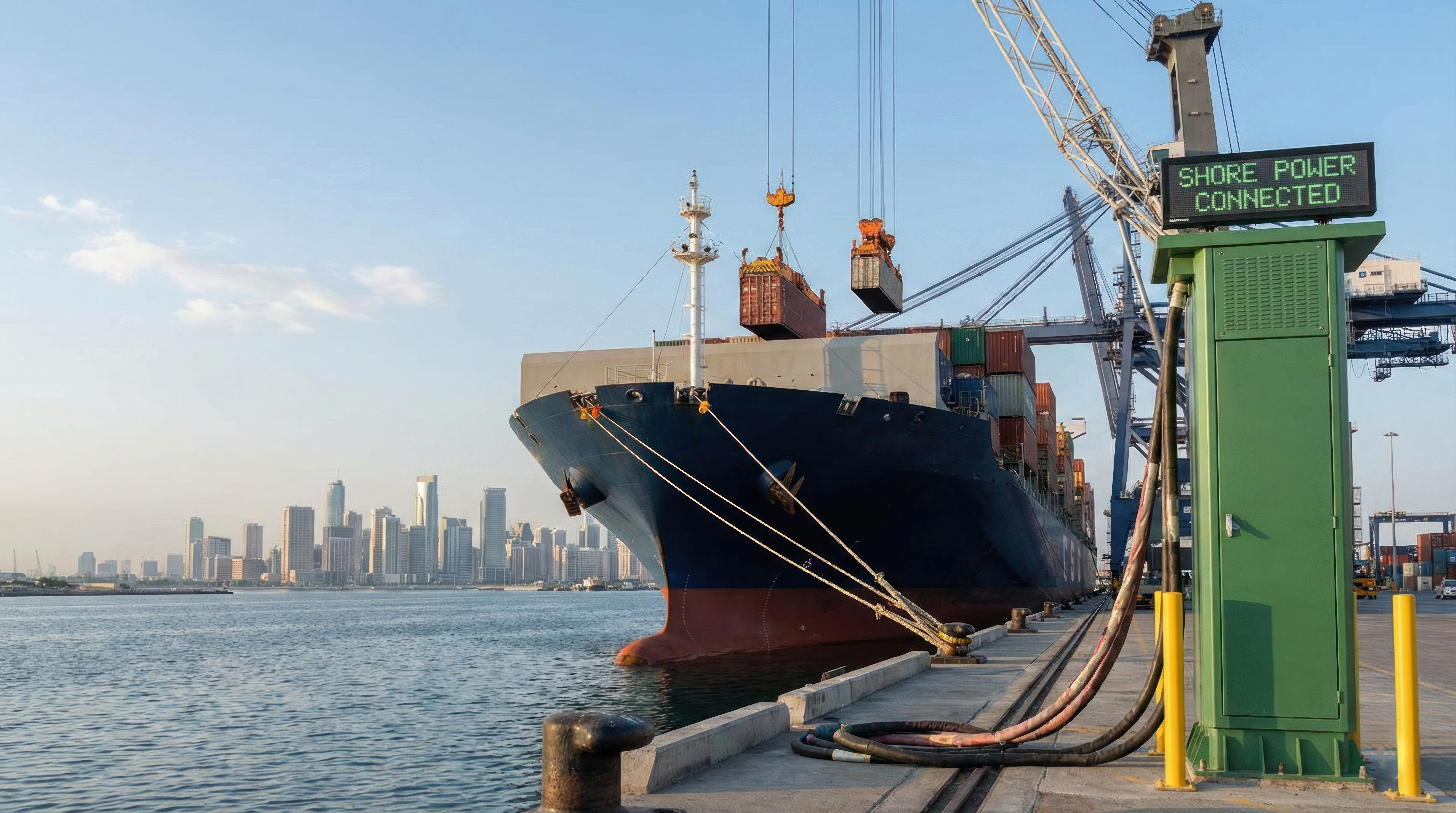
A shore power connection is made and broken thousands of times over the life of a berth, often in salt air, on a wet dock, with the vessel riding the tide. Each time, the connection involves heavy cable being landed by hand or by boom, mated de-energized behind an interlock, then energized against a ship's electrical system whose grounding arrangement is nothing like the shore's. As emissions regulations push shore power (or ”cold ironing”) from optional to mandatory, it is becoming increasingly common at ports, terminals, and berths.
For ESL Power Systems, which builds the mounds behind this connection, and Bender, which supplies much of the instrumentation inside it, maintaining safety comes down to continuous ground-fault monitoring. Whether incorporated into the design of a new berth or added to an existing installation, ground-fault monitoring should be considered an integral part of the shore power electrical system.
How shore-to-ship power works
A shore power system, also called cold ironing, Alternative Maritime Power (AMP), or Onshore Power Supply (OPS), takes power from a dockside substation, through a shore power mound, across a flexible cable on a boom or reel, and onto the vessel's distribution system. The mound is the pedestal-mounted enclosure at the berth, housing the receptacles, safety interlocks, metering, and monitoring equipment.
The scale of these systems varies widely. Naval and Coast Guard berths typically run low-voltage connections through MIL-C-24368 single-pole connectors; cruise and container terminals often run 6.6 kV or 11 kV under IEC/IEEE 80005-1, with 80005-3 covering low-voltage shore connections.
What makes the interface unusual is that the two sides use different system grounding arrangements. Shoreside utility supply is normally solidly grounded (TN or TT in IEC terms), and shipboard distribution has traditionally been ungrounded (or IT, from IEC 60364: "I" for a supply isolated from ground, "T" for exposed conductive parts connected to ground). Many vessels, particularly at higher voltages, use high-resistance grounding instead, limiting ground fault current to a few amps while behaving much like an ungrounded system in service. The distinction matters because the monitoring technology follows the grounding arrangement, not the voltage class.
The reason behind this is operational. In an ungrounded or high-resistance grounded system, a first ground fault doesn't trip the system offline: a vessel with one insulation fault keeps making way and reaches port instead of losing propulsion at sea. This is an advantage; however, it also means a fault could go unnoticed unless something is actively looking for it.

Where the risks concentrate
Several risks converge at the mound, and one gets less attention than it deserves: equipotential bonding. Before a connection is energized, the ship's hull and the shore installation must be brought to the same potential, and that bond needs verifying continuously, not just one time at hookup. IEC/IEEE 80005-1 treats bond monitoring as part of the shore-to-ship protection scheme, with loss of the bond among the conditions that trigger shutdown. A degraded bond is easy to miss because it doesn't announce itself the way a tripped breaker does. This invites stray current and galvanic corrosion on the hull.
The rest is familiar to anyone who has worked a berth:
- Corrosive marine air accelerates insulation breakdown well beyond typical industrial rates.
- Tidal movement and repeated connect/disconnect cycles stress cables, leading to chafing and conductor damage.
- The two grounding arrangements must be reconciled at the interface without weakening either side's protection.
- Dockworkers handle heavy connectors and cable in wet conditions, which is why deenergized mating and interlocking matter as much as monitoring.
- Shore-side and ship-side monitoring must stay coordinated, or a fault could be missed or blamed on the wrong side of the plug.
What ground fault monitoring actually does
The point is to catch insulation degradation while it's still a maintenance item, not an emergency. Ground fault monitoring helps achieve this by identifying electrical problems early, before they cause an unexpected shutdown or safety issue. The type of monitoring depends on how the system is grounded.
On a solidly grounded (TN/TT) system, a Residual Current Monitor (RCM) measures the vector sum of current through the live conductors. In a healthy circuit, that sum is essentially zero, so any imbalance means current is finding a path to ground. An RCM alarms on that leakage well before an RCD or breaker would trip, turning an unplanned outage into a scheduled repair.
On an ungrounded (IT) system, a different device is required: an Insulation Monitoring Device (IMD). Rather than measuring imbalance, an IMD injects a low-level signal and calculates insulation resistance to ground in real time. Because an ungrounded system rides through a first fault, the IMD's job is to get that fault found and cleared before a second one turns it into a short circuit or shock hazard.
Previously, ground detection lamps were used that dim unevenly as a fault developed. This method couldn’t quantify a fault, log a trend, or tell you where it is, and it depended on someone walking past and noticing. Digital monitoring replaces that with measured resistance values, adjustable thresholds, event logs, and remote alerts.
ESL's approach to the infrastructure
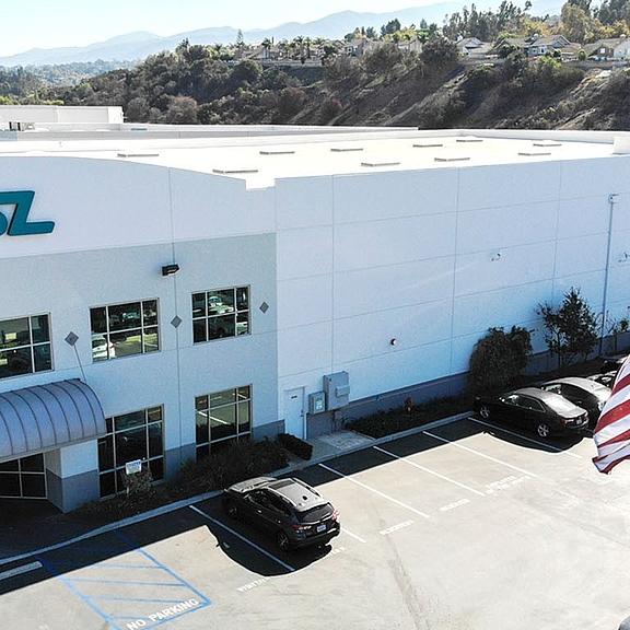
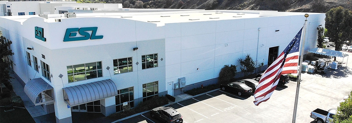
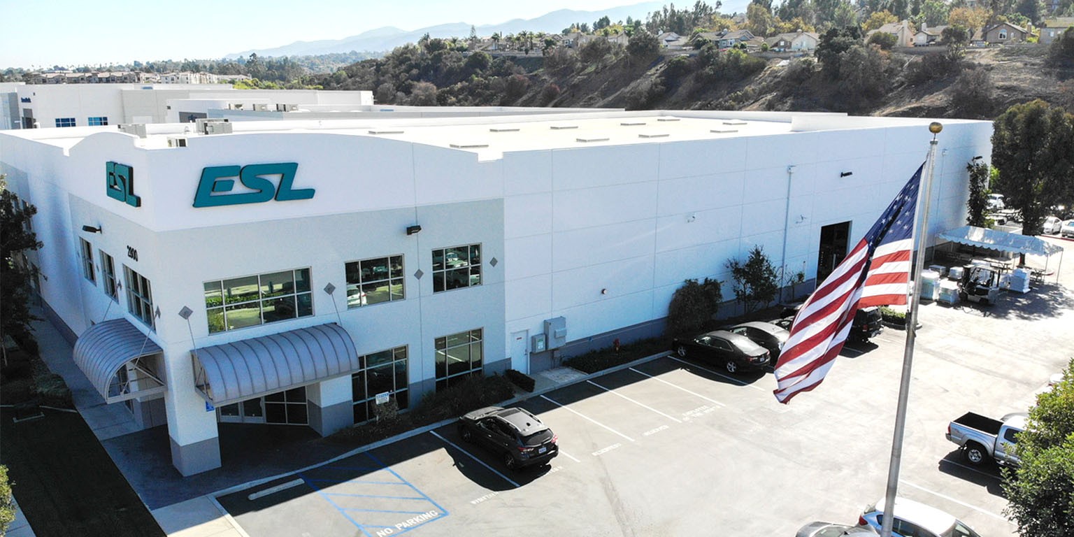
ESL Power Systems is an employee-owned manufacturer in Corona, California, that has spent decades building mounds, hotel stations, and dockside connection equipment for commercial ports, military facilities, and cruise terminals.
ESL's receptacles are safely interlocked, so the circuit is de-energized during insertion and withdrawal, and a connector can't be made or broken under load. Its load centers incorporate insulation monitoring and fault detection into the distribution equipment itself, making the monitoring part of a coordinated, tested assembly rather than a collection of loose devices.
ESL has worked extensively with the Navy and Coast Guard (its MIL-C-24368 plugs and receptacles are NAVSEA QPL-24368 qualified) and with port authorities working through California's At-Berth Regulation and IEC/IEEE 80005. Systems are configured project by project: new mounds for greenfield berths, upgraded load centers and monitoring packages for berths already in service. Retrofits bring their own constraints, such as existing feeders, limited outage windows, integration with whatever SCADA is in place, but those are engineering challenges, not obstacles that can’t be overcome.
Bender instrumentation on both sides of the connection
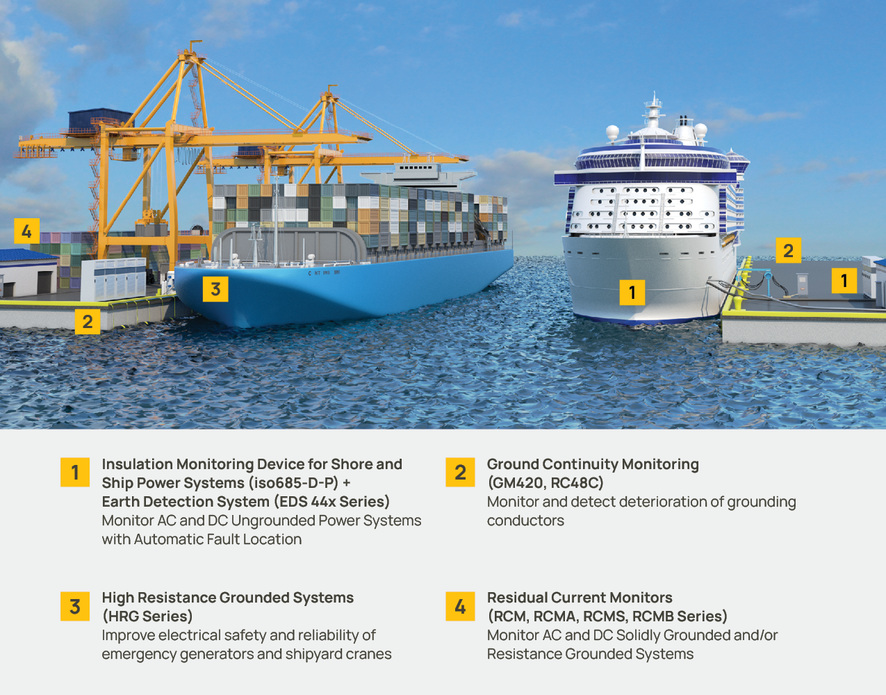
Where ESL provides the physical infrastructure, Bender supplies much of the instrumentation that detects and locates faults.
On the solidly grounded shore side, the Bender LINETRAXX RCMS400 series gives multichannel residual current monitoring across a distribution board, with twelve channels per device, per-channel alarm thresholds, harmonic analysis, and adjustable frequency response. Sensitivity depends on the current transformer chosen per channel: standard CTs cover AC and pulsed DC (Type A), while AC/DC-sensitive CTs are needed for smooth DC residual currents (Type B). Devices report on the Bender BMS bus, with a gateway such as the COM465IP bridging to Modbus/TCP and a web interface.
For bonding and cable integrity, the Bender RC48C combines residual current monitoring with continuous ground-conductor continuity checking in one device. It was built for high resistance-grounded systems and trailing-cable applications, a close analogue to the flexing, repeatedly handled cable at a berth.
On the ship side, the Bender ISOMETER family covers ungrounded systems. The iso685 series is an IMD to IEC 61557-8, applicable to AC, three-phase, AC/DC, and DC systems, including those with rectifiers, inverters, and variable-frequency drives, where older detection methods tend to give unusable readings. It is important to be aware of the rating when specifying: the iso685 covers system voltages to AC 690 V or DC 1000 V, and higher voltages require coupling devices.
Pair the iso685-D-P with ISOSCAN EDS440/441 insulation fault locators and the system does more than flag a fault. The IMD injects a locating pulse, and the EDS units, reading zero-sequence CTs on each feeder, identify which circuit is faulted while the system stays energized, as opposed to the alternative of opening breakers one at a time to hunt for it.
Because shore power briefly joins two different grounding arrangements, coordinating an RCM on the shore side with an IMD on the ship side, with both sets of alarms in front of the same operators, closes a gap either technology alone would leave open.
Bringing it together
Safe, reliable shore power requires more than a secure electrical connection. It requires continuous monitoring of ground faults, insulation issues, and bonding integrity, all within equipment designed for demanding marine environments.
Together, ESL Power Systems and Bender provide the infrastructure and monitoring technology needed to help make shore-to-ship power safer, more reliable, and easier to maintain.
New berth, retrofit, or an existing installation you're not sure is fully monitored? Contact ESL to review your monitoring scheme against the way the berth actually gets used.
At Bender Inc., we’ve been at the forefront of electrical safety for over 80 years. Our commitment to innovation and excellence drives us to create solutions that exceed expectations. When it comes to protecting your facility, trust the experts. Trust Bender.
For more information about this application or to learn more about Bender technology related to your specific application, contact our team of experts.