
Yes, the factory default password is 807.
The information message 8.80 indicates the date and time stamp on the LIM has reverted to default factory settings. Setting the LIM clock will remove the information message. Refer to "Menu Settings" section in the Instruction Bulletin "NAE2025012" for detailed information on setting the Date and Time.
NEC 517.160 (A) (5) Conductor Identification.
The isolated circuit conductors shall be identified as follows:
(1)Isolated Conductor No. 1 — Orange with at least one distinctive colored stripe other than white, green, or gray along the entire length of the conductor
(2)Isolated Conductor No. 2 — Brown with at least one distinctive colored stripe other than white, green, or gray along the entire length of the conductor
The use of XHHN or XHHN-2 wire helps meet this requirement.
Orange shall be terminated on "Neutral" Silver Receptacle Terminal
Brown shall be terminated on "Hot" Brass Receptacle Terminal
It is important to not confuse NFPA 70 definition of "Wet Locations" with the NFPA 99 definition of "Wet Procedure Locations".
NFPA-99:2012 Sections 3.3.184 & 6.3.2.2.8 define Wet Procedure Locations and the requirements for additional protection against electrical shock in these areas.
In a simplistic method, a "Wet Procedure Location" can be determined by evaluating the type of procedures, irrigation and medical equipment planned for use in the particular area.
NFPA 99:2012 Section 6.3.2.2.8.4 defines all Operation Rooms as wet procedure locations, unless a risk assessment conducted by the health care governing body determines otherwise.
An Isolated Power System is required in all NFPA 99:2012 defined "Wet Procedure Locations" when an interruption of power (due to a ground fault) cannot be tolerated. NEC for electrical safety recommends isolated power systems. (Should be installed when ever a power outage cannot be tolerated during a ground fault condition.)
Conductor Identification requirements for isolated (ungrounded) conductors of Isolated Power Systems are identified in NFPA 70 (NEC) in Article 517.160.
NFPA 70 (2008 - current)
NFPA 70 (2005)
It is an ungrounded system so you should expect to get about 50% of the system voltage from either line to ground.
Refer to the NEC for minimum conductor & conduit sizes. Typical 120V circuits are rated for 20A therefore 12 AWG conductors would be appropriate.
3/4" conduit is recommended with no more than 6 conductors (2-circuits) per conduit to help minimize leakage.
Bender recommends Annual Preventive Maintenance of all Isolated Power Panels as well as testing and recertification after any modification to the Isolated Power System.
Bender Annual and Bi-Annual recertification services include, but are not limited to:
Bender Certification Field Testing includes, but is not limited to:
The Medical panels are tested and listed to UL-1047 as a complete piece of equipment. UL-1047 specifies the maximum primary main breaker size, therefore, utilizing a primary main breaker with ampacity exceeding the value specified by UL results in a non-UL compliant product.
The LIM monitors the impedance of the isolated circuit current carrying conductors (Line 1, Line 2) with respect to ground (earth) and indicates (mA) the total current that would flow through a low impedance if it were connected between either Line and ground.
The most common reasons for the LIM to be in alarm are:
Field (Overhead) room lighting circuits should not be supplied from an Isolated Power System. Surgical Lights (articulating arm that could be used for procedure) within the patient space should be connected to the IPS.
The wording as per (NEC-2011) 517.160(A)(4) is only in reference to “Operating Rooms”.
This should be evaluated via a risk assessment. There are two (2) thoughts on this subject.
It is recommended to avoid using the transformer compartment as a "wire way" for conductors. In the event that wire must be run in the transformer compartment the following must be adhered:
- Limit the amount of cross wiring as much as possible
- Maintain segregation by separation between the Grounded (Main) conductors and all ungrounded (branch) conductors
Conductor Identification requirements for isolated (ungrounded) conductors of Isolated Power Systems are identified in NFPA 70 (NEC) in Article 517.160.
NFPA 70 (2008 - current)
Isolated Conductor No. 1 — Orange with at least one distinctive colored stripe other than white, green, or gray along the entire length of the conductor
Isolated Conductor No. 2 — Brown with at least one distinctive colored stripe other than white, green, or gray along the entire length of the conductor
NFPA 70 (2005)
Isolated Conductor No. 1 — Orange
Isolated Conductor No. 2 — Brown
It is recommended to avoid using ANY wire pulling compound for isolated (ungrounded) conductors of an Isolated Power System.
Wire-Pulling Compound requirements for isolated (ungrounded) conductors of Isolated Power Systems is identified in NFPA 70 (NEC) in Article 517.160.
- Compounds that increase the dielectric constant shall NOT be used on the secondary conductors of the isolated power supply.
- Compounds known to increase the dielectric constant include but are not limited to:
- Polymer/Water Types
- Wax/Wax Soap Types
- Dry Talc Types (results in minimal increase in dielectric constant)
Each termination and splice of a conductor decreases the impedance of the circuit.
It is recommended to avoid wire splicing for isolated (ungrounded) conductors of an Isolated Power System. In the event that wire splicing is unavoidable it is recommended to:
- Utilize compression type terminals only.
The quantities will, except for rare occasions, not be equal for several reasons: 1. The proximity of each (L1 and L2) conductor to ground will be different when running the wires in conduit; therefore, the line-to-ground capacitance will also be different. Running twisted pairs of conductors (twisted) at roughly 2-foot intervals is a good approach for achieving symmetrical line-to-ground capacitances. 2. Not all circuits have loads that can be turned ON and OFF with DPST (double pole single throw) switches. Therefore, loads with SPST (single pole single throw) switches that are in the OFF state add to the line-to-ground capacitance between only one of the isolated power conductor and ground. 3. Loads are often designed to be powered from a grounded instead of an isolated supply. A line-to-ground filter is often added between the HOT wire and ground. This approach for attenuating electrical noise further adds to the asymmetry between line-to-ground capacitances.
No.
Ground-Fault Circuit-Interrupters (GFCIs) are intended for protection of personnel, for use only in grounded neutral systems in accordance with the National Electrical Code (NEC).
Many power strips incorporate "surge suppression" by utilizing MOVs (metal oxide varistors) which are notorious for causing high levels of leakage currents. An isolated power system will not operate properly with a surge protective device installed.
Refer to individual detail drawings of the particular panel for the exact location of the main circuit breaker.
NEC-2011 Section 404.8(A) indicates the breaker's center of the operating handle, when it's in its highest position, shall be located no more than 2.0m (6ft 7in) above the floor.
No, locations not defined as “Operating Rooms” do not need to be served by a dedicated IPS.
480ft is recommended; see supplemental information
Yes.
Per (NEC-2011) 517.13(B)(1) an Insulated Equipment Grounding Conductor (sized in accordance with 250.122) is required to be directly connected to the following:
- the grounding terminals of all receptacles.
- metal boxes and enclosures containing receptacles
- all non–current-carrying conductive surfaces of fixed electrical equipment likely to become energized that are subject to personal contact, operating at over 100 volts
exception: an insulated equipment bonding jumper that directly connects to the equipment grounding conductor is permitted to connect the box and receptacle(s) to the equipment grounding conductor
No.
AHJs have the official authority and duty to enforce compliance with a standard or code, and to approve the use of systems.
BENDER is not the Authority Having Jurisdiction "AHJ". BENDER technicians evaluate and test the system for performance and installation deficiencies. Installation methods varying from the approved methods per NFPA 99 and NFPA 70 (NEC) are noted on the report.
Yes, the warranty will still be valid.
As per (NEC-2014) 517.16 Isolated Ground Receptacles shall not be installed within the patient care vicinity
THHN or TFFN conductors are recommended.
Up to 150 ft ---> up to 2 remotes ---> 18AWG
Up to 150 ft ---> 3 remotes ---> 16AWG
150 - 200ft ---> up to 2 remotes ---> 16AWG
150 - 200ft ---> 3 remotes ---> 14AWG
Designers often select resistance grounding to meet code requirements. Portable equipment used in mining for example are often required to be fed from a resistance grounded source. This in addition to ground conductor monitoring and tripping immediately on ground-fault occurrence, help protect employees that are in contact with this equipment and earth.
Awareness of arc flash potential and knowing that 80-90% of faults in a plant start out as a phase-to-ground failure has meant many customers are using high resistance grounding to increase safety. Refineries, pipelines, shore-to-ship power, pulp, paper and forestry industries, steel mills and many other industrial customers have successfully used resistance grounding.
Resistance grounding, in particular, high resistance grounding has a major advantage over solidly grounding by limiting the amount of energy released during a single phase-to-ground fault. While it doesn’t reduce the PPE required for electricians it can add to employee safety and equipment reliability.
Like any mechanical device, grounding resistors can fail due to age, vibration, corrosion and other external causes such as lightning. The ground-fault protection on grounded systems is typically current transformer (CT) based and requires a return path to the source in order for current to flow.
Some sites have a standard that requires them to operate medium voltage with low resistance grounding. In some cases it was a requirement to allow operation of non-sensitive ground fault protection devices. Frequently 400 A grounding resistors are used and the breaker’s standard ground-fault function is usually adequate to detect and trip during a ground fault when there is such high current available.
Yes modern ground-fault protection devices with more sensitive ground-fault pickup levels can detect high resistance faults before they reach a level that causes extensive damage. The correct CT selection can also allow detection of faults on non-linear loads that may be outside of the standard 60 Hz pickup that some ground-fault relays are tuned to.
NGR’s are often mounted outdoors near the main power transformer feeding a facility. They can be even more remote on a moveable substation. Communications to the devices is of great value to customers to give them diagnostics information at their desk or even mobile device.
This is a common question and since many systems are grounded by a resistor that limits current to 10 A or 5 A it seems that a small conductor should be adequate. However you must insure your choice meets the local electrical code requirements. In many cases this means a conductor no less than #8 AWG should be used for grounding.
In more advanced NGR systems the relays will provide the level of fault current, the frequency of the fault current and the phase that the fault is appearing on. If they are also equipped with downstream ground-fault protection it will direct you to the correct feeder, MCC or even load that has the fault.
While continuity of service is one major benefit of both resistance grounding and ungrounded systems that ability should not be abused. Running with a ground fault on a system indefinitely is NOT a good idea. Many sites have a timer set on their alarms. If ground-fault alarms are not cleared in a certain number of hours then the system will start to trip. Having ground-fault tripping on non-critical circuits is a recommended to lower the probability of having a phase-to-phase fault, another good safety by design improvement that could be incorporated in systems.
Yes, the CD14400 coupling device is suitable for both high- and low-resistance grounded systems. It is designed to work with the NGRM series. For HRG (High Resistance Grounded) systems, we offer the NGRM500 and NGRM700, while the NGRM550 and NGRM750 are designed for LRG (Low Resistance Grounded) systems. While there is no specific cut off value for HRG vs LRG systems, in general systems up to 20A are considered HRG and any system above that is considered as LRG.
No single type of ground-fault detector works on every type of power system. For instance, a residual current monitor (RCM) ground-fault relay (GFR) in combination with a zero-sequence current transformer (CT) can be used on solidly grounded or resistance grounded systems, but will need very special consideration if employed on an ungrounded (floating) system. Similarly, an insulation monitoring device (IMD) can be used on an ungrounded system, but will nuisance trip or false alarm in a grounded system.
When residual current monitoring is used, residual and fault currents are signaled before the installation has to be disconnected in the event of a fault. This way, deteriorations of the insulation level are detected at an early stage and in a reliable way.
A comprehensive readiness for operation around the clock, constant competitive pressure and high cost pressure require the highest degree of electrical safety in the power supply of industrial, functional, and residential buildings. With continuous monitoring of safety-relevant circuits for fault currents, residual currents, and stray currents, incipient critical operating states are detected at an early stage. A potential risk of personal injury, fire damage, and material damage as well as EMC interferences can thus be avoided.
The operating theory behind the relay is as follows: The power wires leading to the protected load are passed through a current transformer (CT). It is important that all hot and neutral wires are fed through the CT, and that ground conductors are not. This applies to both, single and three-phase systems, and CT’s used in this fashion are sometimes referred to as zero-sequence CT’s.
Active IMD’s are like an online mega-ohmmeter. They connect between the system phase conductors and ground. A measuring signal is constantly applied to the phase conductors and will detect an insulation fault anywhere on the system from the secondary side of the supply transformer to the connected loads. If this signal finds a path to ground, it will return to the monitor. The IMDs internal circuitry processes the return signal and trips a set of indicators when the set point is exceeded. IMDs measure in Ohms (Resistance) and not in Amps (Current). A ground fault will be indicated as “insulation breakdown”.
All Goods supplied by Seller to Buyer according to the applicable Order Confirmation shall be warranted according to Bender’s Warranty and Returns Statement.
The majority of our products are UL listed or UL recognized. Most of the products carry UL508 listing. Bender Inc. is also an approved UL508A - Control Panel Manufacturer.
The AMP measurement method patented for Bender is based on a special clocked measuring voltage which is controlled by a micro-controller and adapts automatically to the prevailing system conditions. Software-based evaluation enables system leakage currents causing interference on the evaluation circuit to be differentiated from the measured variable proportionate to the insulation resistance in ohms. This means that broadband interferences as they occur, for example, during converter operation, do not adversely affect the precise determination of the insulation resistance.
The AMP Plus measurement method takes interference suppression to the next level. Devices supporting this measurement method can be used universally in AC, DC and AC/DC systems, e.g. systems with varying voltages or frequencies, high system leakage capacitances or DC voltage components. This makes them ideal for use in today's state-of-the-art distribution systems, which are usually subject to this type of interference (converters, EMC).
There is no required time interval for calibration. However, we recommend performing an offset calibration if the CT has been moved (this calibration procedure only applies to the CTBC series). While not mandatory, testing your circuit every few months is a good practice to ensure proper operation and system health. Also, remember that the ground conductor should never pass through the CT!
Yes! The iso685 is an excellent choice for monitoring insulation values in your system. We offer several Bender IMDs (Insulation Monitoring Devices) for ground fault monitoring in ungrounded systems. These devices help protect people and equipment while preventing costly downtime. Additionally, we provide variants that detect and locate ground faults.
Yes, the LG2 is compatible with VFDs. For optimal performance, we recommend placing the LG unit on the line side of the drive to detect any downstream ground faults.
No single type of ground-fault detector works on every type of power system. For instance, a residual current monitor (RCM) ground-fault relay (GFR) in combination with a zero-sequence current transformer (CT) can be used on solidly grounded or resistance grounded systems but will need very special consideration if employed on an ungrounded (floating) system. Similarly, an insulation monitoring device (IMD) can be used on an ungrounded system, but will nuisance trip or false alarm in a grounded system.
All Goods supplied by Seller to Buyer according to the applicable Order Confirmation shall be warranted according to Bender’s Warranty and Returns Statement.
Majority of our products are UL listed, or UL recognized. Most of the products carry UL508 listing. Bender Inc. is also an approved UL508A - Control Panel Manufacturer.
Most Bender devices do not require yearly calibrations / calibrations at all there are a couple of exceptions to this (NGRM devices are calibrated during startup) also for the (AC/DC CT there is an offset calibration but only when required please consult a Bender Technical support before calibration).
There is no time interval for calibrations. However, we do recommend doing an offset calibration if the Current Transformer has been moved. Overall, it's ideal to test your circuit every few months just to make sure everything is operating correctly. Although this is not mandatory, it is good to run tests to ensure your system is healthy and the CT is working properly.
The measuring range varies depending on what RCM is being used. However, the range for your CT is typically 100 mA…10 A. In terms of frequency filtering the devices we offer with that option are the RCMB300, RCMS410, and RCMS460/490. I have attached the links below and datasheets.
The difference is that alarm 1 is a pre-alarm which will alert that there is a fault on the system or that the insulation value has hit the targeted number set by the end user. Whereas alarm 2 is the alarm that is designated to be the main alarm in ungrounded systems it can heighten the alert of a fault.
Designers often select resistance grounding to meet code requirements. Portable equipment used in mining for example is often required to be fed from a resistance grounded source. This, in addition to ground conductor monitoring and tripping immediately on ground-fault occurrence, help protect employees that are in contact with this equipment and earth. Resistance grounding, in particular, high resistance grounding has a major advantage over solid grounding by limiting the amount of energy released during a single phase-to-ground fault. While it doesn’t reduce the PPE required for electricians it can add to employee safety and equipment reliability
Awareness of arc flash potential and knowing that 80-90% of faults in a plant start out as a phase-to-ground failure has meant many customers are using high resistance grounding to increase safety. Refineries, pipelines, shore-to-ship power, pulp, paper and forestry industries, steel mills and many other industrial customers have successfully used resistance grounding.
Like any mechanical device, grounding resistors can fail due to age, vibration, corrosion and other external causes such as lightning. The ground-fault protection on grounded systems is typically current transformer (CT) based and requires a return path to the source for current to flow.
Some sites have a standard that requires them to operate medium voltage with low resistance grounding. In some cases, it was a requirement to allow operation of non-sensitive ground fault protection devices. Frequently 400 A grounding resistors are used, and the breaker’s standard ground-fault function is usually adequate to detect and trip during a ground fault when there is such high current available. Whereas with a High resistance grounding (HRG) which limits the fault-current to a lower value usually 1-10A. In addition, the HRG also have time duty of continuous meaning that with the first fault the system with still continue operation whereas in a LRG the time duty is around 10s -60s.
NGR’s are often mounted outdoors near the main power transformer feeding a facility. They can be even more remote on a moveable substation. Communications with the devices is of great value to customers to give them diagnostics information at their desk or even mobile device. With this being said Bender offers a network gateway device that allows for remote communication through Bender’s Web interface. Which can be used to pull data through Modbus RTU/TCP, to Bender’s web interface or third party BMS.
This is a common question and since many systems are grounded by a resistor that limits current to 10 A or 5 A it seems that a small conductor should be adequate. However, you must ensure your choice meets the local electrical code requirements. In many cases this means a conductor no less than #8 AWG should be used for grounding.
In more advanced NGR systems the relays will provide the level of fault current, the frequency of the fault current and the phase that the fault is appearing on. If they are also equipped with downstream ground fault protection it will direct you to the correct feeder, MCC or even load that has the fault.
While continuity of service is one major benefit of both resistance grounding and ungrounded systems, that ability should not be abused. Running with a ground fault on a system indefinitely is NOT a good idea. Many sites have a timer set on their alarms. If ground-fault alarms are not cleared in a certain number of hours, then the system will start to trip. Having ground-fault tripping on non-critical circuits is a recommended to lower the probability of having a phase-to-phase fault, another good safety by design improvement that could be incorporated in systems.
When residual current monitoring is used, residual and fault currents are signaled before the installation must be disconnected in the event of a fault. This way, deteriorations of the insulation level are detected at an early stage and in a reliable way.
A comprehensive readiness for operation around the clock, constant competitive pressure and high cost pressure require the highest degree of electrical safety in the power supply of industrial, functional, and residential buildings. With continuous monitoring of safety-relevant circuits for fault currents, residual currents, and stray currents, incipient critical operating states are detected at an early stage. A potential risk of personal injury, fire damage, and material damage as well as EMC interferences can thus be avoided.
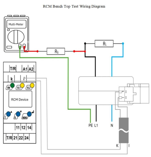
This test setup verifies proper operation of a Residual Current Monitor (RCM) by introducing a controlled leakage current from line to ground. A resistive load limits system current for safe testing, while a calculated leakage resistor creates a known ground fault current (10 mA). The RCM reading is compared against a multimeter measurement to confirm accurate leakage detection within acceptable tolerance.
Use a minimum 5 W rated resistor for both R_L and R_g during this test.
1. Power the device using terminals A1 | A2 in accordance with the specified control voltage requirements.
2. Connect the current transformer (CT) to the K | I terminals on the device.
3. Ensure L1 (Line) and N (Neutral) are correctly connected from the source. This test assumes a Hot/Neutral system configuration for simplicity.
4. Route both L1 and N through the current transformer as shown, terminating at the resistive load R_L. For safety, the test current is limited to 20 mA. At 120 V, this corresponds to:
5. R_L = 120 V / 20 mA = 6 kΩ.
6. If the source voltage differs, adjust R_L accordingly to maintain 20 mA.
7. Connect the leakage resistor R_g from the load side of L1 to the multimeter at the red node, as shown in the diagram.
8. Connect the green node from Protective Earth (PE/GND) to the multimeter as indicated.
9. Calculate R_g based on the desired leakage current. A default leakage current of 10 mA is used for this test:
10. R_g = 120 V / 10 mA = 12 kΩ.
11. After verifying all connections, energize the device and then apply source power. The RCM should immediately indicate an alarm corresponding to approximately 10 mA of leakage current. The multimeter should also measure approximately 10 mA.
12. If the leakage current indicated by the RCM matches the multimeter reading within ±5%, the device is operating correctly. Minor variation may occur due to impedance tolerances.
The operating theory behind the relay is as follows: The power wires leading to the protected load are passed through a current transformer (CT). It is important that all hot and neutral wires are fed through the CT, and that ground conductors are not. This applies to both single and three-phase systems, and CT’s used in this fashion are sometimes referred to as zero-sequence CT’s.
The current carrying conductors should be run through the CT, also, remember that the ground conductor should never pass through the CT!
The direction that the Bender CT’s should be placed is P1 facing the Supply side of the system where P2 should face the load side of the system.
The maximum length that is allowed from the CT to the RCM is 40 meters it is recommended to keep them as close as possible for the most accurate readings. This only applies to AC only current transformers. If we are using an AC/DC type CT also known as Type B, then the distance is 10 meters.
The recommended approach is to place the CT before the VFD, this ensures the entire system is measured not just the load. You must be mindful that the VFD might have some leakage current. Since the CT is placed on the line side of the VFD, this current will be seen but the Bender device. Make sure to consult with the VFD manufacturer or manual to see what the expected leakage current is. If leakage current from the drive is too high, you may need to reconsider the placement of the CT to the load side of the VFD (NOTE: this approach will no longer provide detection for the drive but only for what is downstream of the CT.
Yes, most of our newer RCM devices such as the RCMB3xx or RCMS410 have a built in filter. Filtering allows for any unwanted leakage currents such as high harmonic noise from a VFD drive to be blocked out. A device like the RCMS410 has a built-in band-pass filter. For further information, please reach out to our technical support team.
Yes, it is best to center the cables through the CT per recommended manufacturers spec. While not having the wires fully centered, especially in AC only systems is not a huge issue, depending on the application, it may lead to inaccurate readings.
Our units can be adjusted to your needs. Generally, an AHJ, Code or specifying engineers will provide these requirements. It is recommended to consult with these entities before setting up any response values.
Voltage is not a limiting factor on the RCM units and neither is the current load. The limiting factor is the leakage current of the system and the physical limitation of the CT. Additionally our units have 800V insulated rating, so if the units are near a bare bus bar the bus bar should be insulated properly it should be at least 2x the outer diameter, please refer to the local code for anymore sizing.
Active IMD’s are like an online mega-ohmmeter. They connect between the system phase conductors and ground. A milli-volt measuring signal is constantly applied to the phase conductors and will detect an insulation fault anywhere on the system from the secondary side of the supply transformer to the connected loads. If this signal finds a path to ground, it will return to the monitor. The IMDs internal circuitry processes the return signal and trips a set of indicators when the set point is exceeded. IMDs measure in Ohms (Resistance) and not in Amps (Current). A ground fault will be indicated as “insulation breakdown”.
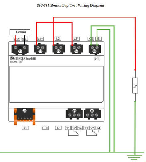
This procedure verifies proper operation of the ISO685 insulation monitoring device by applying a known resistance between the monitored system terminals and protective earth. A user-defined resistor is used to simulate an insulation fault, allowing the measured insulation value displayed by the ISO685 to be directly compared to the applied resistance. This test confirms the correct insulation measurement functionality in a controlled environment.
1. Isolate the ISO685 from the system. This test must only be performed with the device completely disconnected from any live installation and in a controlled environment.
2. Jumper L1, L2, and L3 together directly at the ISO685 measurement terminals.
3. Connect a test resistor between the jumped L1/L2/L3 node and Protective Earth (PE). One end of the resistor connects to the combined L1/L2/L3 terminal, and the opposite end connects to PE (ground). This resistor simulates a known insulation resistance to earth. This test can also be done with a decade box.
4. Select a resistor value appropriate for the desired test point. Typical values are greater than or equal to 10 kΩ. The resistor value directly determines the insulation resistance reading.
5. Connect terminals KE and E individually to Protective Earth (PE).
6. Power the ISO685 using the specified control supply voltage.
7. Allow the device to complete its startup sequence. After several seconds, the ISO685 will detect the simulated insulation fault and display the measured insulation resistance.
8. Verify that the insulation resistance displayed by the ISO685 approximately matches the applied resistor value. For example, a 10 kΩ resistor connected between L1/L2/L3 and PE should result in an insulation resistance reading of approximately 10 kΩ.
Important Notes:
Yes, Bender does have solutions for location on an ungrounded system using the EDS-440 and CT’s there is a solution that allows for location detection as finite as the specific branch that is faulting.
The AMP measurement method patented for Bender is based on a special clocked measuring voltage which is controlled by a micro-controller and adapts automatically to the prevailing system conditions. Software-based evaluation enables system leakage currents causing interference on the evaluation circuit to be differentiated from the measured variable proportionate to the insulation resistance in ohms. This means that broadband interferences as they occur, for example, during converter operation, do not adversely affect the precise determination of the insulation resistance.
The AMP Plus measurement method takes interference suppression to the next level. Devices supporting this measurement method can be used universally in AC, DC and AC/DC systems, e.g. systems with varying voltages or frequencies, high system leakage capacitances or DC voltage components. This makes them ideal for use in today's state-of-the-art distribution systems, which are usually subject to this type of interference (converters, EMC).
Yes, the polarity of the supply power connection matters A1/+ and A2/-. In the case of external supply, the device can be supplied either via A1/+ and A2/- or via X1. In the case of supply via A1/+ and A2/-, make sure that +24V is applied to A1 and A2 is connected to GND (ground). Providing Power via X1 it is also polarity sensitive, use should provide power at both terminals A1/A2 and X1 at the same time.
No, the iso415R-24 power supply is not internally galvanically isolated so the unit must have its own dedicated, isolated, ungrounded power supply. The unit has an internal power supply (DC 12… 48V) and therefore does not need to be operated with a separate power supply.
The difference is that for coupler monitoring is part of the iso685 that monitors the connection between the line of the system and the device to make sure that it is able to measure the system you are looking to protect. When the feature is on and connection is lost then error of check L1/L2/L3 will appear on the device.
Coupling Selection is designed to be used when you have a coupler attached to the iso685 device to extend monitoring range of the device to a high system voltage that can be measured. When using a coupler coupling monitoring should be turned off.
Yes, you can connect multiple IMD’s to multiple units but only with specific variants i.e. the iso685-X-B & iso685-X-P have a feature built in that allows for the decoupling of the devices from the system. If there are two or more units present in the system, make sure isoNet/ isoLoop should be configured.
Because the iso685 has an active measurement pulse, it does not need system voltage to measure it does need low impedance between the lines that it is connected to. If the bus is completely dead or open meaning all the phases are isolated to each then the device throws a check L1/L2/L3 connection error.
While there is no strict distance measurement it is recommended to have the coupler close to the iso685 so that there is no voltage drop over a long run.
Make sure there is proper wiring and line side of the contact primarily the first two terminals on the left depending on the voltage being brought across the contactor, units leave the factory at 480V, If the voltage is not tapped correctly the contactor may hum, buzz, or chatter.
LG come with a few fuses the fuse that is missed the most is a pull out fuse this fuse supply’s power to the Bender devices.
Generally, shows up when using units that have an RCMA421H it usually means that there is a welded contactor or in very rare occasions there is an internal failure of the unit.
This device is used to work together with the W35-BS Current Transformer the units are calibrated at the factory to work as a pair replacing only one instead of both will cause issues.
No, the units come with a built-in contactor, there is no need for a shunt trip breaker on this unit. Shunt trip breakers are to be used in conjunction with our MarinaGuard units – refer to this page for more information on our Marina Guards
While Bender does sell the GFGC Panel Bender does not sell the ground clamp/pilot wire, please reach out local rep or distributor.
The shunt trip breakers should be rated for continuous operation and having a momentary shunt trip can potentially damage the unit.
Bender does not recommend changing any parts in the field, making any adjustments or repairs to the units that can affect their operation, additionally modification of the devices will void any warranty. Except for fuses they can be replaced with no repercussions. These devices have a two-year warranty if there are any questions, please reach out to our technical support team.
The iso175 supports different CAN protocols depending on the variant, including standard Bender CAN and SAE J1939.
An abbreviation for Electrical vehicle supply equipment, also known as an EV charger.
Level 2 chargers are also known as AC chargers. They can be found as wall boxes in homes or often in public in front of shopping centers and hotels. AC voltage is at 240 V with a maximum current of 80 A and a maximum power of 19.2 kW. These are more powerful than a typical level 1 emergency charge cord. Charging times on these are usually measured in a few hours.
Level 3 chargers are also known as DC fast chargers. Their high power level allows for relatively fast top off below 30 minutes. Powerlevels are usually in the above 100 KW range and require a utility style power backing. These are relatively big, with units that can easily reach the dimension of a typical refrigerator. Modern level 3 are often equipped with Chademo (Asian standard) and CCS (Western standard) connectors/plugs.
This is the North American standard for EV connectors and covers the physical, electrical and communication requirements for the conductive charge system.
This is Underwriters Standard for Safety for Personnel Protection Systems for Electric Vehicle (EV) Supply Circuits: Particular Requirements for Protection Devices for Use in Charging Systems. It describes how a EVSE will have to be designed to pass Uls rigorous safety tests and requirements.
The Chademo system originated as a competitor to CCS for a fast charging DC system. While similar, there are subtle differences limiting it to models like the Nissan Leaf and Toyato Prius amongst others. While the original standard described delivering up to 125A of direct current at up to 500V into a vehicle, the upgraded Chademo 2 can utilize nowadays up to 1000VDc and 400A. All this, with the target to charge a vehicle in the shortest possible time.
The combined Charging System CCS covers EVs using Combo 1 and 2 connectors up to 350KW in a DC fast charging system. It represents one of three systems available to the public, besides Tesla and Chademo. Like the Chademo the power levels. Currently maxed out at 350KW of available power it only lags a little behind the Chademo who tops out at 400KW.
Y capacitances are present between a high voltage DC system in a vehicle and the chassis. Usually caused by filter circuits or battery capacitance, it is the goal of an EV manufacturer to keep those low, while balancing their need to produce noise reduction. Passenger vehicle Y caps are usually below 1uF, whereas busses and trucks with their larger systems can go up to 5uF.
A US standard specifying performance requirements for EVs. Specifically listing recommended values for isolation from High voltage. Originally just a paper for testing an EV, but its contents and figures have migrated over into newer documents and modern EV safety standards.
Requirements are 100Ohm/ volt for pure DC, 500Ohm / volt for mixed AC/DC systems. For safety reasons usually the higher value of 500 is chosen. What does that mean for the operator of an EV? If an EV has let’s say a 700V battery, then the isolation between the high voltage system and the battery frame must be higher than 700V x 500 = 350000 Ohms. If that value is decreased for whatever reason, an isolation fault alarm will be triggered and the vehicle needs to be inspected.