Type B Ground-Fault Protection for Variable Frequency Drives
Variable frequency drives (VFDs), also referred to as adjustable frequency drives (AFDs), improve motor control and energy efficiency across industrial facilities. However, the power electronics inside a drive also change the electrical characteristics of the system - including the ground-fault currents that protective devices must detect.
Traditional ground-fault relays were developed primarily for sinusoidal AC systems operating at 50 or 60 Hz. A VFD can produce DC, pulsed DC, high-frequency and mixed-frequency ground-fault currents that may not be accurately detected by conventional AC-sensitive devices.
For facilities using VFDs, selecting the correct ground-fault monitoring technology and current transformer placement is essential for reliable fault detection.
How Ground-Fault Current Changes Across a VFD
A VFD first converts incoming AC power to DC and then uses pulse-width modulation to produce a controlled output to the windings of the motor to control its rotational speed. Because of this conversion process, the waveform associated with any possible ground fault depends on where the fault occurs within the power conversion process.
A ground fault on the line side of the drive will generally resemble the incoming 60 Hz waveform. A fault within the DC link can produce a rectified or rippled DC current. A fault in the motor cable or motor can contain pulse-width-modulated currents with multiple frequencies. This means a single drive system can produce several significantly different ground-fault waveforms.
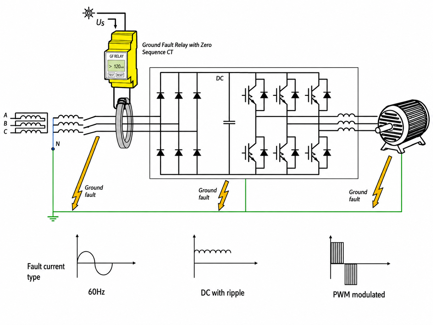
Type A residual current devices are designed primarily to detect sinusoidal AC, pulsating sinusoidal currents and certain pulsating DC currents. They may not accurately register DC-link or load-side faults created by a VFD. Conventional ground-fault relays that rely on narrow frequency ranges or bandpass filters may have even more limitations depending on the frequencies they are designed to detect.
Understanding DC Blinding
A particular concern in drive applications is “DC blinding”.
Traditional Type A current transformers are passive devices. When DC ground-fault current passes through the transformer, it can pre-magnetize the ferrous core and move it toward magnetic saturation. Once the core becomes saturated, a larger AC fault current may be required to produce a response—or operation may be inhibited entirely.
The ground-fault sensing system can therefore become less sensitive at the same time a fault is present.
Type B monitoring technology addresses this limitation through active measurement and compensation. Rather than relying solely on a passive current transformer, Type B devices are powered and can measure true RMS values across AC, DC and mixed-frequency waveforms.
High-Frequency Leakage and Nuisance Alarms
VFDs commonly include filters that limit electromagnetic interference. These filters may use capacitor-resistor networks that allow a controlled amount of high-frequency current to flow to ground.
Carrier frequencies are often in the kilohertz range, far beyond the 60 Hz waveform associated with traditional power distribution. Depending on the sensing technology and installation point, this high-frequency leakage can produce elevated readings, nuisance alarms or nuisance tripping.
Increasing the relay’s pickup setting may appear to resolve the problem, but it can also make the system less sensitive to actual insulation deterioration and lower-level ground faults.
A properly selected Type B ground-fault monitor can distinguish and accurately measure the wider frequency spectrum associated with power-electronic equipment.
Where Should the Current Transformer Be Installed?
For most non-isolated VFD applications, the Type B current transformer should be installed on the line side of the drive.
A current transformer detects ground faults downstream of its installation point. Installing it ahead of the VFD places the drive, motor cable and motor within the monitored zone. It also allows the drive’s internal filters to reduce unwanted high-frequency components before they reach the monitoring device.
A CT installed on the load side monitors only the outgoing cable and motor. It is also exposed to the full pulse-width-modulated output and associated high-frequency leakage, which can result in higher measured values and an increased potential for nuisance alarms.
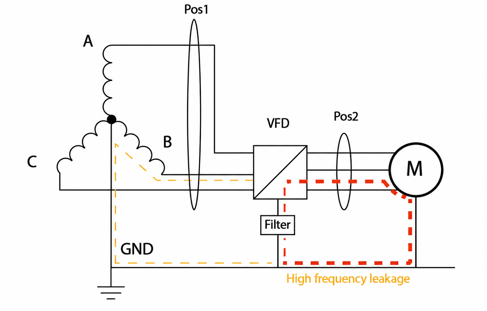
All current-carrying conductors (including the neutral when one is present) must pass through the Type B measuring current transformer. The protective equipment grounding conductor must not pass through the CT. Under normal operation, the vector sum of the current through the monitored conductors is zero. Any current returning through another path, including ground, appears as residual current.
Ground-Fault Monitoring on High-Resistance Grounded Systems
Ground-fault detection becomes even more challenging when VFDs are supplied by a high-resistance grounded system.
A neutral grounding resistor intentionally limits the available ground-fault current, often to 10 A or less. In some pulp and paper applications, the system may be limited to 5 A or below. Rectification within the VFD can further reduce the alternating component measured by an AC-sensitive ground-fault relay.
If the first ground fault is not detected, it may remain in the system until a second fault occurs on another phase. The second fault can create a phase-to-phase current path and cause considerably more damage.
Early detection of AC, DC, rectified and high-resistance ground faults gives maintenance personnel time to investigate and repair the first fault before it escalates.
The white paper also notes that UL 1053 primarily addresses ground-fault sensing and relaying equipment for solidly grounded systems. Its testing requirements do not fully define the frequency response needed for the range of waveforms encountered in VFD and resistance-grounded applications.
Bender Ground-Fault Monitoring Solutions for VFD Applications
Bender offers AC/DC-sensitive ground-fault monitoring devices for grounded electrical systems. The appropriate solution depends on the number of drives, required alarm outputs, current range, communications requirements and whether monitoring or protective tripping is required.
For a single VFD or feeder, the LINETRAXX® RCMA420 or RCMA423 can provide AC/DC-sensitive ground-fault monitoring when paired with the appropriate Bender measuring current transformer. Both devices are identified by Bender as AC/DC ground-fault monitors.
For facilities monitoring multiple drives or feeders, the LINETRAXX® RCMS460-D Blindspot® provides multi-channel AC/DC ground-fault monitoring. The RCMS490-D Blindspot® adds individual relay outputs, allowing each monitored circuit to initiate a separate alarm or control response.
Reliable Detection Requires the Right Technology
VFDs introduce waveform characteristics that conventional AC ground-fault relays may not be designed to detect. DC components can saturate passive current transformers, while high-frequency leakage can create inaccurate readings and nuisance alarms.
Type B ground-fault monitoring provides AC/DC-sensitive measurement across the complex waveforms associated with modern drives. When the current transformer is correctly selected and positioned—typically on the line side of the VFD—the system can monitor the drive, motor cable and motor while reducing exposure to unwanted high-frequency leakage.
Bender’s AC/DC-sensitive ground-fault monitoring solutions provide the visibility required to detect developing faults earlier, reduce troubleshooting time and help prevent a first ground fault from escalating into a more serious event.
At Bender Inc., we have been advancing electrical safety technology for more than 80 years. Our ground-fault monitoring solutions help facilities identify electrical problems before they lead to equipment damage, unplanned downtime, or safety hazards.
For assistance selecting a ground-fault monitor and current transformer for your VFD application, contact the Bender team. For more information on electrical safety for motor control equipment, click here.
This article is for informational purposes only. Bender provides the information “as is” without warranty and is not responsible for its accuracy or reliability. No warranties are given regarding its suitability for any specific circumstances.